
Powering Neon with a Joule Thief

Joule thief are small, fun circuits which exploit a few characteristics of electronics and LEDs in order to “steal” virtually all of the energy stored in a battery. They can operate at incredibly small voltages and are fairly simple to make. With a few modifications to this basic circuit it’s possible to drive other things than an LED, though, like this joule thief that lights up a neon bulb.

The circuit from [suedbunker] aka [fuselage] is based on a pin from the Chaos Communication Camp which had a standard LED. To get a neon light to illuminate a few modifications to the standard joule thief are needed.

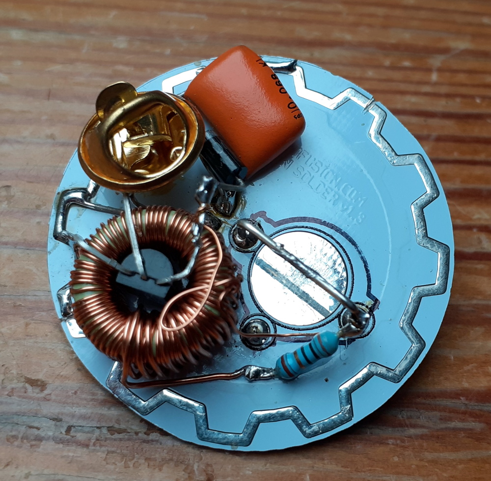
First, the windings have to be changed from 10:10 to 10:80 to increase the voltage across the bulb. Second, a transistor with slightly different characteristics was used than the original design. The capacitor was also replaced with a larger one.

While it might seem simple, the physics of how a joule thief works are anything but, and modifying the delicate circuit to work with something other than an LED is commendable. It also has a steampunk vibe which is a cool look even in projects that don’t involve steam at all.


from Hackaday https://ift.tt/39RVFrv

Comments

Popular posts from this blog

How To Play Doom – And More – On An NES

Doom was a breakthrough game for its time, and became so popular that now it’s essentially the “Banana For Scale” of hardware hacking. Doom has been ported to countless devices, most of which have enough processing ability to run the game natively. Recently, this lineup of Doom-compatible devices expanded to include the NES even though the system definitely doesn’t have enough capability to run it without special help. And if you want your own Doom NES cartridge, this video will show you how to build it . We featured the original build from [TheRasteri] a while back which goes into details about how it’s possible to run such a resource-intensive game on a comparatively weak system. You just have to enter the cheat code “RASPI”. After all the heavy lifting is done, it’s time to put it into a realistic-looking cartridge. To get everything to fit in the donor cartridge, first the ICs in the cartridge were removed (except the lockout IC) and replaced with custom ROM chips. Some modifica...

Bill Gates steps down from Microsoft’s board to focus on philanthropy

In an announcement on Friday, Microsoft revealed that company co-founder Bill Gates has decided to step down from his role on its Board of Directors in order to focus on his philanthropic efforts at the Bill & Melinda Gates Foundation. This is Gate’s biggest change to his role at Microsoft since stepping down as company chairman in February 2014. According … Continue reading from SlashGear https://ift.tt/2We90Gu

The Flexible Permanence of Copper Tape Circuits

Somewhere between shoving components into a breadboard temporarily and committing them to a piece of protoboard or a PCB lies the copper tape method. This flexible Manhattan-style method of circuitry formed the basis for [Bunnie Huang]’s Chibitronics startup, and has since inspired many to stop etching boards and start fetching hoards of copper tape. [Hales] hit the ground running when he learned about this method , and has made many a copper tape circuit in the last year or so. He offers several nice tips on his site that speak from experience with this method, and he’ll even show you how to easily work an SMD breakout board into the mix. Generally speaking, [Hales] prefers plywood as the substrate to paper or cardboard for durability. He starts by drawing out the circuit and planning where all the tape traces will go and how wide they need to be. Then he lays out copper traces and pads, rubs the tape against the substrate to make it adhere strongly, and reinforces joints and laps w...